
info@smarledlighting.com
+86 20 38466982
Toggle Navigation
By Dale Chaw | SMAR LED Lighting
Technical Review: SMAR LED Lighting Engineering Team
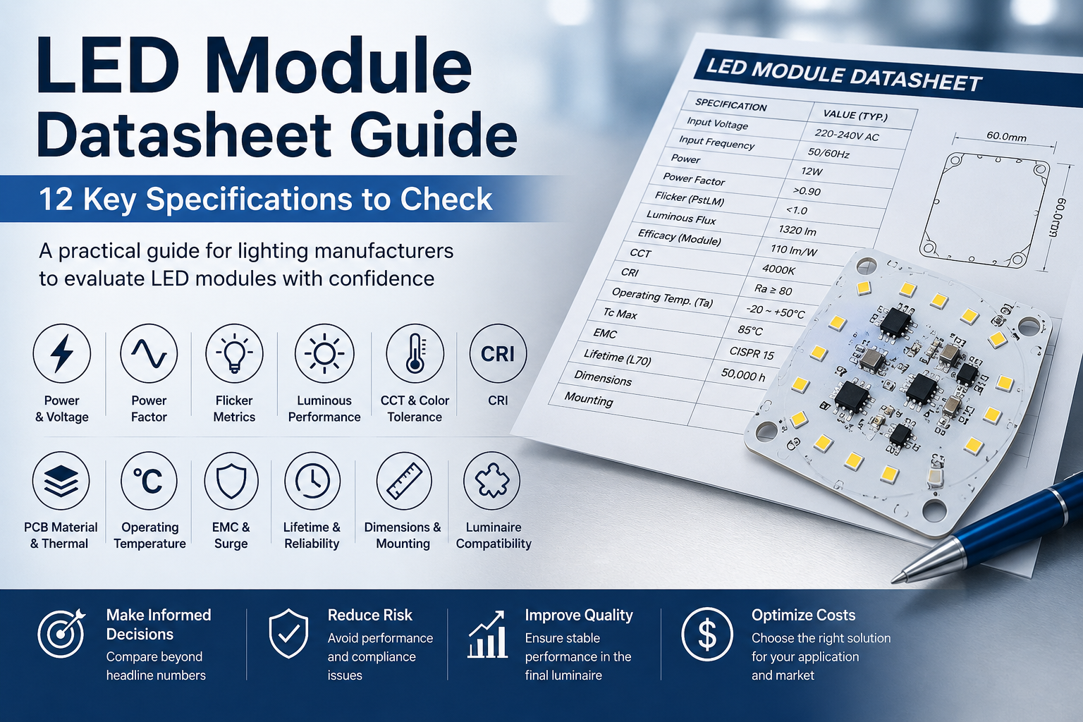
An LED module datasheet may look simple: power, voltage, power factor, luminous flux, CCT, CRI, and dimensions.
But the numbers alone rarely tell the full story.
Two LED modules may both be described as 12W, 4000K, CRI 80, and 120 lm/W—yet perform very differently in the same luminaire.
One may maintain stable power across the required voltage range, operate at a lower temperature, and meet flicker and EMC requirements. The other may produce unacceptable flicker, develop thermal problems, or require redesign before certification.
The difference often lies behind the headline specifications:
How and under what conditions was the power measured?
Is the stated efficacy for the LED chip, module, or complete luminaire?
Does a high power factor also mean low flicker?
Was thermal performance measured in free air or inside the final fixture?
Are EMC, surge, and lifetime claims supported by relevant test conditions?
For lighting manufacturers, a datasheet should be treated as a starting point for engineering evaluation—not as proof of final product performance.
This guide explains 12 specifications that manufacturers, product managers, and buyers should check before approving an LED module for mass production.
1. Input Power vs Rated Power
Power is often the first specification buyers compare—and one of the easiest to misunderstand.
A module described as “12W” may refer to:
nominal or rated power
actual AC input power
LED output power
maximum operating power
These values are not necessarily the same.
For an AC-input DOB module, the most relevant figure is usually the actual input power measured under defined operating conditions.
A nominal 12W module may measure 11.2W, 12.0W, or 12.8W depending on input voltage, component tolerances, operating temperature, and circuit design. A small variation may be acceptable, but the measurement conditions must be clear.
Before comparing two modules, check:
actual input power
measurement voltage and frequency
power tolerance
cold-start versus thermally stabilized performance
consistency across production samples
These details become especially important when power affects energy-efficiency requirements, thermal design, or customer specifications.
A rated power value without defined test conditions is incomplete information.
2. Input Voltage and Frequency
A specification such as 220–240V AC, 50/60Hz should mean more than simply that the module can turn on throughout this range.
It should also maintain acceptable performance.
Input voltage variation may affect:
input power and LED current
power factor
flicker
light output
component temperature
A module that performs well at 230V may behave differently at 220V or 240V. Depending on the circuit design, power, current ripple, PF, or thermal stress may change near the operating limits.
For projects intended for multiple markets, the required voltage and frequency range should therefore be confirmed before circuit development.
From Our Engineering Experience: In customized LED module projects, we evaluate electrical performance across the required voltage range rather than only at 230V. A module that appears stable at nominal voltage may show different power, PF, or flicker behavior near the upper or lower limit.
Testing only at nominal voltage can hide problems that appear in real operating conditions.
3. Power Factor
Power factor (PF) is one of the most frequently requested specifications for AC LED modules.
Depending on the application and market requirements, buyers may request:
PF > 0.5
PF > 0.7
PF > 0.9
However, a higher PF is not automatically better for every project.
Achieving PF > 0.9 may require a different circuit topology or additional components, affecting BOM cost, PCB space, circuit complexity, and overall performance.
The correct PF target should therefore be based on the actual product and regulatory requirements—not simply the highest possible number.
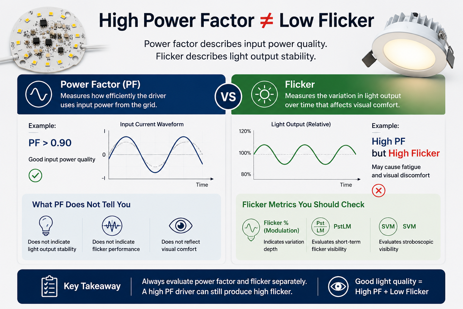
High PF Does Not Mean Flicker-Free
A module can have PF > 0.9 and still produce unacceptable flicker.
Power factor describes electrical behavior at the input. Flicker describes variation in light output over time. They are influenced by the same driver system, but they are not the same performance parameter.
A datasheet showing only:
PF: 0.95
does not provide enough information to evaluate light stability.
From Our Engineering Experience: Different circuit approaches can achieve different PF targets, but they may also change cost and flicker performance. We therefore evaluate PF and flicker separately rather than assuming that improving one automatically improves the other.
For more detail, see our guide to flicker-free LED modules and flicker evaluation.
[Internal Link: Flicker-Free LED Modules: Why They Matter for Modern Lighting]
4. Flicker Metrics
Terms such as flicker-free, low flicker, and no visible flicker are not always based on the same measurement method.
Professional projects should rely on measurable data rather than marketing descriptions.
Common metrics include:
Flicker Percentage or Modulation
This indicates the variation between maximum and minimum light output but does not fully describe how people perceive flicker at different frequencies.
PstLM
PstLM evaluates short-term flicker visibility under defined conditions. A lower value generally indicates better performance.
SVM
The Stroboscopic Visibility Measure evaluates stroboscopic effects that may become visible when objects move under the light.
Flicker should ideally be evaluated:
across the required voltage range
after thermal stabilization
under dimming conditions, if applicable
using measurable metrics such as PstLM and SVM
Where applicable, products for the European market should also be evaluated against relevant Ecodesign requirements.
A short test at nominal voltage and room temperature may not reveal problems that appear when voltage or temperature changes.
“Flicker-free” should be supported by test data, not treated as a descriptive label.
5. Luminous Flux and System Efficacy
Efficiency figures are among the most misunderstood numbers in LED lighting.
A supplier may state:
220 lm/W
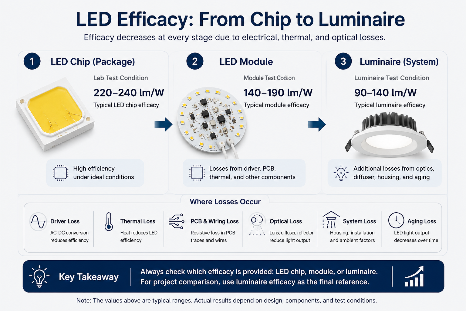
But this could refer to:
LED chip or package efficacy
LED module efficacy
complete luminaire efficacy
These values can be very different.
A high-efficiency LED package does not mean the complete module will achieve the same lm/W. Module performance is affected by LED operating current, driver efficiency, temperature, and electrical losses. The complete luminaire introduces further losses from diffusers, lenses, reflectors, and covers.
For example, an LED package may be rated at 220 lm/W under laboratory conditions. Once mounted on a PCB and operated at the actual design current and temperature, module efficacy will normally be lower. After installation behind a diffuser or optical system, complete luminaire efficacy will be lower again.
This does not necessarily indicate a poor product. It reflects different measurement levels.
When reviewing a datasheet, ask:
Is this LED efficacy, module efficacy, or luminaire efficacy?
An integrating sphere report is usually more useful than a single lm/W figure because power, luminous flux, efficacy, CCT, and CRI can be evaluated together.
From Our Engineering Experience: In one low-power module project, increasing the LED quantity and reducing the operating stress per LED improved the measured module efficacy. The result could not be understood from the nominal LED chip specification alone; the operating point, input power, temperature, and integrating sphere data had to be evaluated together.
6. CCT and Color Tolerance
CCT, or Correlated Color Temperature, describes the general appearance of white light. Common values range from warm white at 2700K or 3000K to neutral white at 4000K and cooler light at 5000K or 6500K.
But CCT alone does not guarantee that two modules will look identical.
Two modules can both be specified as 4000K and still show a visible color difference because a nominal CCT represents a range rather than one exact color point.
For projects requiring tighter consistency, buyers may also need to evaluate:
chromaticity coordinates
SDCM
MacAdam ellipses
LED binning
A smaller SDCM range generally indicates tighter color consistency.
This is particularly important when many luminaires are visible together, such as in linear lighting, offices, retail stores, hotels, and architectural projects.
Production control also matters. Even when initial samples match well, uncontrolled mixing of LED batches may create visible differences during mass production or repeat orders.
Do not stop at:
CCT: 4000K
Also ask what color tolerance applies, whether SDCM is specified, and how LED batches are controlled.
For many professional projects, consistent color across hundreds of luminaires is more important than a small difference in initial luminous efficacy.
7. CRI: Color Rendering Index
CRI, or Color Rendering Index, describes how accurately a light source reproduces colors compared with a reference light source.
CRI 80 is widely used for general lighting, while retail, hospitality, residential, and other color-sensitive applications may require CRI 90 or higher.
However, higher CRI usually involves trade-offs. A high-CRI LED may have lower luminous efficacy and higher cost than a standard CRI 80 solution.
Two modules with the same input power may therefore produce different luminous flux if they use different CRI levels.
When reviewing a datasheet, evaluate CRI, luminous flux, CCT, and color consistency together. The highest CRI is not automatically the best choice if the application does not require it.
8. PCB Material and Thermal Conductivity
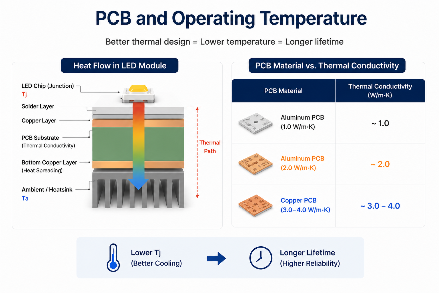
The PCB is not simply a mounting surface. It is part of the module’s thermal path.
Common options include FR4, aluminum PCB, and higher-performance metal-core PCB solutions. For many commercial lighting products, aluminum PCB is preferred because it transfers heat more effectively than standard FR4.
However, a datasheet stating only:
Aluminum PCB
does not provide enough information.
Important specifications may include:
thermal conductivity
PCB thickness
copper thickness
dielectric quality
Higher thermal conductivity can improve heat transfer, but it does not automatically guarantee a lower LED temperature. Actual performance also depends on power density, component layout, thermal interface, heat-sink contact, and the final luminaire structure.
A properly integrated 1W/mK PCB may perform better than a 2W/mK PCB with poor thermal contact.
The right question is therefore not:
“Is 2W/mK better than 1W/mK?”
It is:
“Is this PCB suitable for the power density and thermal design of the complete product?”
For a detailed comparison, see our guide to LED PCB materials, thermal conductivity, and copper thickness.
[Internal Link: LED PCB Materials Explained: How to Choose the Best PCB for Different Lighting Applications]
9. Operating Temperature: Ta, Tc and Tp
Temperature specifications are among the most important—and most frequently misunderstood—parts of an LED module datasheet.
Depending on the product, you may see:
Ta — ambient temperature
Tc — case temperature or specified case measurement point
Tp — designated temperature measurement point
These terms are not interchangeable.
Ta describes the surrounding environment. The same module may operate very differently in a 25°C laboratory and a 50°C industrial environment.
Tc or Tp refers to a defined measurement point on the product. The exact location matters. Measuring a convenient area of the PCB instead of the specified point or actual hot spot may produce an overly optimistic result.
Why Free-Air Testing Can Be Misleading
A module tested on an open bench may run much cooler than the same module inside the final fixture.
The final luminaire may have limited airflow, a compact housing, a diffuser or cover, nearby heat-generating components, and different contact with the heat sink.
When reviewing thermal data, confirm:
ambient temperature
measurement point
test duration
mounting conditions
whether the module reached thermal stability
From Our Engineering Experience: We evaluate thermal images after the module reaches a stable operating temperature and focus on localized hot spots rather than only the average PCB temperature. In integrated DOB designs, the hottest point may be an electronic component rather than the LED itself.
10. EMC and Surge Requirements
A module may meet its power, PF, efficacy, and flicker targets—and still fail EMC testing.
Depending on the product and target market, evaluation may include:
conducted emissions
radiated emissions
harmonic current requirements
immunity
surge performance
For many lighting products, CISPR 15 / EN 55015 are relevant references for electromagnetic disturbance requirements.
EMC performance should not always be judged from the bare module alone. Results may change because of wire routing, PCB layout, housing structure, grounding, nearby components, and the final luminaire assembly. This is particularly important for radiated emissions.
Surge requirements also depend on the application. An indoor residential luminaire and an outdoor street light do not operate in the same electrical environment.
When reviewing EMC information, confirm:
which requirements were evaluated
whether testing used the module or complete luminaire
the test configuration and input conditions
the surge level, where relevant
whether test reports or pre-compliance data are available
From Our Engineering Experience: During prototype development, conducted and radiated emission testing can identify potential noise problems before final approval. A simple “EMC compliant” statement is less useful than knowing the test method, product configuration, and compliance margin.
For more detail, see our guide to EMC requirements for LED modules.
[Internal Link: Why EMC Matters for LED Modules and How to Choose the Right Solution]
11. Lifetime and Lumen Maintenance
A datasheet may claim:
Lifetime: 50,000 hours
But how was this number determined?
For LED products, lifetime does not always mean complete failure. It may refer to lumen maintenance, commonly expressed as L70, L80, or L90.
For example, L70 refers to the point at which the light source maintains 70% of its initial output under defined conditions.
LED package data such as LM-80 and projections using TM-21 can provide useful references. However, complete module lifetime also depends on:
LED operating current and temperature
driver components
PCB and thermal design
surge protection
manufacturing quality
the luminaire environment
A high-quality LED package cannot compensate for an overheated driver IC, unstable current, or another component that ages prematurely.
When evaluating a lifetime claim, ask three questions:
Is it based on LED package data or complete module performance?
What operating temperature was assumed?
Which component is most likely to limit system lifetime?
LED module lifetime is a system-level result, not a single component specification.
For a complete discussion, see our guide to LED module lifetime and long-term reliability.
[Internal Link: LED Module Lifetime Explained: 7 Engineering Factors That Determine Long-Term Reliability]
12. Dimensions, Mounting and Luminaire Compatibility
Electrical and optical performance receive most of the attention, but mechanical compatibility can determine whether a module is practical for mass production.
Important specifications include:
PCB dimensions and thickness
mounting-hole positions
maximum component height
wire-entry position and connector type
LED layout and optical alignment
A difference of only a few millimeters may affect heat-sink contact, lens positioning, diffuser uniformity, wiring, assembly, or existing tooling.
Two modules may have similar outer dimensions but different mounting points or component layouts. A component positioned too close to the housing may create an assembly or thermal problem, while a different LED arrangement may affect the existing lens or diffuser.
Before sample approval, confirm the mechanical drawing, mounting dimensions, component height, LED position, wiring requirements, thermal contact area, and compatibility with the final housing.
For customized projects, sharing the luminaire drawing or available installation space early can reduce unnecessary redesign.
A technically good LED module is not the right solution unless it also fits the product mechanically, thermally, and optically.
A Real Example: Why Two “12W LED Modules” Can Perform Very Differently
Consider a lighting manufacturer looking for a customized 12W LED module with similar PCB dimensions, 220–240V AC input, and defined CCT, CRI, and luminous output requirements.
On paper, several products may appear almost identical.
In reality, different circuit approaches can produce very different results.
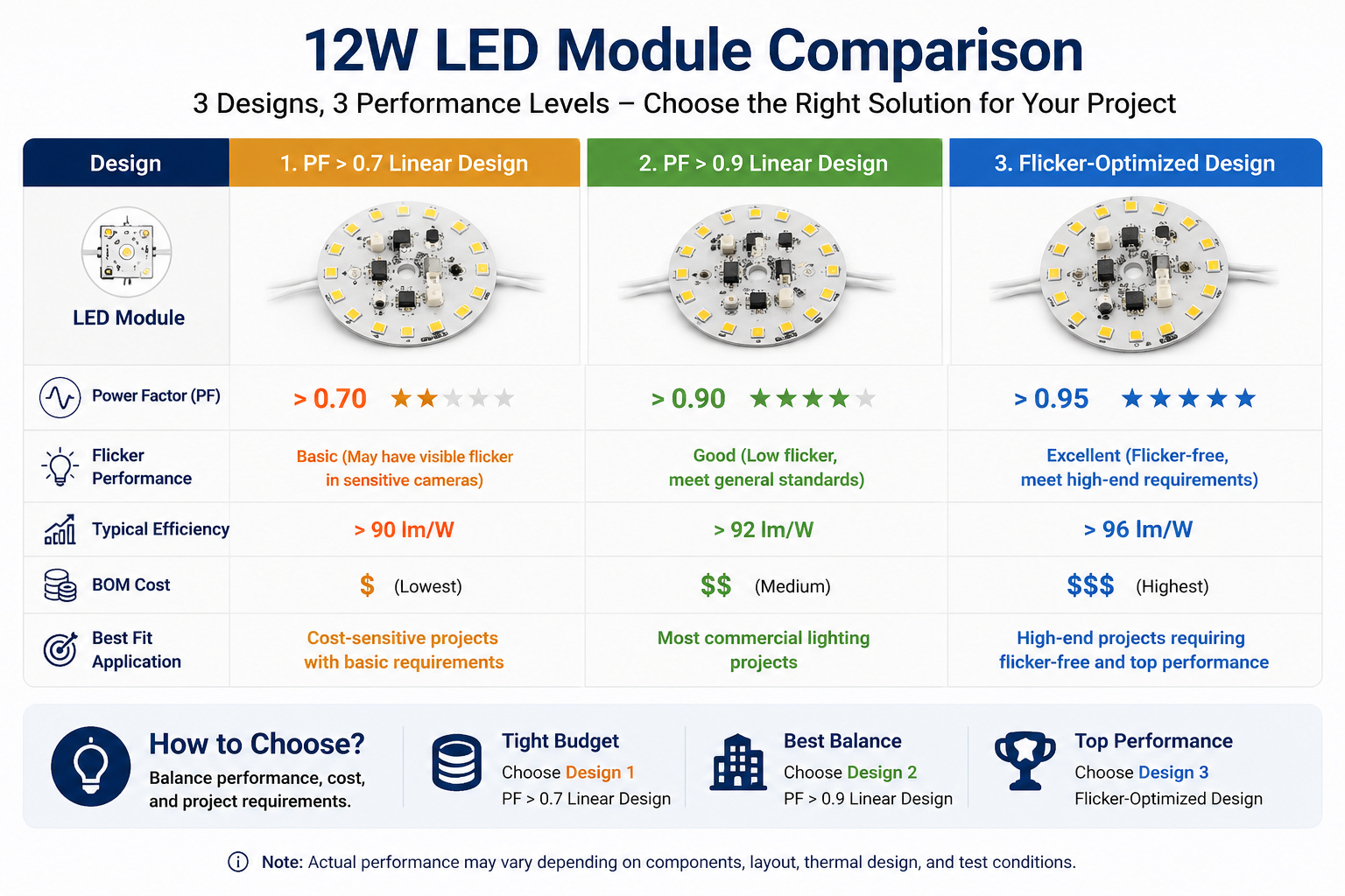
Option A: Linear Design with PF >0.7
A lower-cost solution for applications without strict high-PF requirements.
Option B: Linear Design with PF >0.9
The higher PF may require a different circuit design or additional components, increasing cost and complexity. Flicker must still be evaluated separately.
Option C: Non-Isolated, Flicker-Optimized Design
A solution designed with low flicker as a priority. Its circuit topology, cost, EMC behavior, and application suitability differ from the other two options.
All three could still be described as:
12W LED Module, 220–240V, 4000K, CRI 80
Yet the headline specifications hide important differences:
Specification | Option A | Option B | Option C |
Power Factor | >0.7 | >0.9 | Depends on design |
Flicker | Must be tested | Must be tested separately | Key design priority |
Cost | Lower | Higher | Usually higher |
Circuit Design | Simpler | More complex | Different topology |
EMC | Requires validation | Requires validation | Requires validation |
Best Fit | Cost-sensitive projects | High-PF requirements | Low-flicker requirements |
The key point is not that one solution is always superior.
The correct choice depends on the target market, application, certification requirements, performance priorities, and budget.
A professional evaluation should therefore begin not with:
“Which option has the lowest price?”
but with:
“Which specifications actually matter for this lighting product?”
A higher-cost solution may reduce certification risk, improve visual performance, or avoid redesign. On the other hand, paying for PF >0.9 or a more complex circuit when the application does not require it may add unnecessary cost.
From Our Engineering Experience: We often compare different circuit approaches before finalizing a customized module. Differences in PF, flicker, cost, thermal behavior, and EMC requirements can make one solution more suitable than another even when the wattage and dimensions are almost identical.
This is why custom LED module development should consider the complete project rather than unit price alone.
[Internal Link: Custom LED Modules vs Standard LED Modules: Which One Really Saves Money?]
LED Module Datasheet Checklist
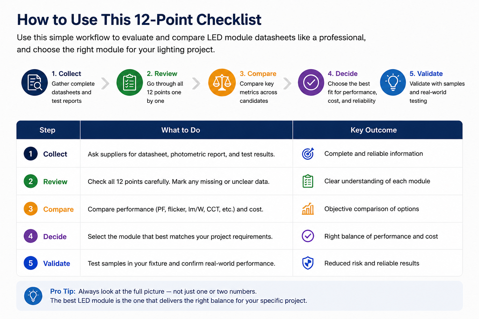
Before approving an LED module, verify these 12 areas:
Input Power — actual power, tolerance, and test conditions
Voltage and Frequency — performance across the required range
Power Factor — the right target for the application
Flicker — measurable data, not only marketing claims
Luminous Performance — chip, module, or luminaire efficacy
CCT and Color Tolerance — consistency, not only nominal CCT
CRI — appropriate color quality for the application
PCB Material — suitability for the thermal system
Operating Temperature — Ta, Tc/Tp, and actual test conditions
EMC and Surge —requirements for the target market
Lifetime —the basis of the lifetime claim
Mechanical Compatibility — mounting, optics, thermal contact, and assembly
Every important datasheet value should answer three questions:
What was measured?
Under what conditions?
Does it match the final application?
Conclusion
An LED module datasheet is an essential evaluation tool, but headline specifications alone do not prove that a module is suitable for a particular product.
Two modules with the same wattage, CCT, CRI, and dimensions may perform differently because of their circuit design, flicker, thermal behavior, EMC performance, and mechanical compatibility.
Before mass production, combine datasheet review with sample testing under conditions that reflect the final luminaire.
At SMAR LED Lighting, we develop customized LED PCB, DOB module, COB module, and LED module solutions for lighting manufacturers and OEM/ODM projects, covering prototype development, electrical and photometric evaluation, thermal testing, flicker testing, EMC evaluation, and design optimization.
A good datasheet tells you what a product is supposed to do. Good engineering verifies what it actually does.
About the Author
Dale Chaw works with lighting manufacturers and OEM buyers on customized LED PCB, DOB module, COB module, and LED module projects at SMAR LED Lighting. Her work covers product requirements, sample development, testing coordination, and communication with engineering and production teams.
Connect with Dale on LinkedIn:
Feed | LinkedIn